|
Tamaño: 7233
Comentario:
|
Tamaño: 2698
Comentario:
|
| Los textos eliminados se marcan así. | Los textos añadidos se marcan así. |
| Línea 15: | Línea 15: |
| {{{ | |
| Línea 17: | Línea 16: |
| /* Carlos Soto check 3/05/11 Manejo LCD */ |
<<BR>><<BR>> === Montaje del programa para Manejo de LCD === |
| Línea 23: | Línea 19: |
| * [[hlpd/curso_arduino/fuentes/caf0020401|enlace al código]] * [[http://wiki.cenditel.gob.ve/wiki/hlpd/curso_arduino/fuentes?action=AttachFile&do=view&target=hapa02.sch|enlace a diagrama]] <<BR>><<BR>> |
|
| Línea 24: | Línea 23: |
| //Este programa maneja la LCD con un arduino mega | === Circuito de Conexión -LCD- === |
| Línea 26: | Línea 25: |
| #include <Wire.h> | {{attachment:lcd2.png}} |
| Línea 28: | Línea 27: |
| int dd=50; #define expander B0100000 // Direccion del expansor alpha-num // 0 1 0 0 A2 A1 A0 // 0 1 0 0 0 0 0 // Note that the R/W bit is not part of this address. |
=== Materiales === |
| Línea 34: | Línea 29: |
| // include the library code: #include <LiquidCrystal.h> |
* Pantalla LCD * Arduino * Resistencia 220 ohm |
| Línea 37: | Línea 33: |
| // initialize the library with the numbers of the interface pins LiquidCrystal lcd(13, 12, 11, 10, 9, 8); |
<<BR>><<BR>><<BR>><<BR>> |
| Línea 40: | Línea 35: |
| //Manejo de Entradas const int inPin01 = 4; const int inPin02 = 5; const int inPin03 = 6; const int inPin04 = 7; //Manejo de Entradas en setup int inState01 = 0; int inState02 = 0; int inState03 = 0; int inState04 = 0; |
=== Montaje del programa para Manejo de LCD y 4 Pulsadores === |
| Línea 51: | Línea 37: |
| * [[hlpd/curso_arduino/fuentes/caf0020402|enlace al código]] * [[http://wiki.cenditel.gob.ve/wiki/hlpd/curso_arduino/fuentes?action=AttachFile&do=view&target=lcd_4pulsar.sch|enlace a diagrama]] <<BR>><<BR>> |
|
| Línea 54: | Línea 41: |
| void setup() { Wire.begin(); Serial.begin(9600); |
=== Circuito de Conexión -LCD+4pulsar- === |
| Línea 58: | Línea 43: |
| // set up the LCD's number of rows and columns: lcd.begin(16, 2); // Print a message to the LCD. lcd.print("HAPA 001"); } |
{{attachment:lcd4pulsar.png}} |
| Línea 64: | Línea 45: |
| void loop() { | === Materiales === |
| Línea 66: | Línea 47: |
| inState01 = digitalRead(inPin01); inState02 = digitalRead(inPin02); inState03 = digitalRead(inPin03); inState04 = digitalRead(inPin04); if (inState04 == LOW) { // turn LED on: lcd.setCursor(5, 1); // print the number of seconds since reset: lcd.print("cuatro"); } else if (inState03 == LOW) { // turn LED on: lcd.setCursor(5, 1); // print the number of seconds since reset: lcd.print("tres"); } else if (inState02 == LOW) { // turn LED on: lcd.setCursor(5, 1); // print the number of seconds since reset: lcd.print("dos"); } else if (inState01 == LOW) { // turn LED on: lcd.setCursor(5, 1); // print the number of seconds since reset: lcd.print("uno"); } else { // turn LED on: lcd.setCursor(5, 1); // print the number of seconds since reset: lcd.print(" "); } // set the cursor to column 0, line 1 // (note: line 1 is the second row, since counting begins with 0): lcd.setCursor(0, 1); // print the number of seconds since reset: lcd.print(millis()/1000); |
* Pantalla LCD * Arduino * Resistencia 220 ohm * 4 Pulsadores * Resistencia 1100 ohm |
| Línea 117: | Línea 55: |
| } | <<BR>><<BR>><<BR>><<BR>> |
| Línea 122: | Línea 60: |
| }}} | |
| Línea 124: | Línea 61: |
=== Montaje del programa para Manejo de arreglo de siete segmentos === * [[hlpd/curso_arduino/fuentes/caf0020403|enlace al código]] * [[http://wiki.cenditel.gob.ve/wiki/hlpd/curso_arduino/fuentes?action=AttachFile&do=view&target=lcd_4pulsar.sch|falta diagrama]] |
|
| Línea 125: | Línea 67: |
| === Manejo de LCD === | |
| Línea 127: | Línea 68: |
| [[hlpd/curso_arduino/fuentes/caf0020401|enlace al código]] <<BR>><<BR>> === Manejo de arreglo de siete segmentos === |
=== Circuito de Conexión -Arreglo siete segmentos- === |
| Línea 134: | Línea 72: |
| {{{ /* * Print "HOLA" into 7 segment array display * * (c) 2010 Alberto Medrano (alberto@cenditel.gob.ve) * CENDITEL Foundation * * This program is free software: you can redistribute it and/or modify * it under the terms of the GNU General Public License as published by * the Free Software Foundation, either version 3 of the License, or * (at your option) any later version. * * This program is distributed in the hope that it will be useful, * but WITHOUT ANY WARRANTY; without even the implied warranty of * MERCHANTABILITY or FITNESS FOR A PARTICULAR PURPOSE. See the * GNU General Public License for more details. * * You should have received a copy of the GNU General Public License * along with this program. If not, see <http://www.gnu.org/licenses/>. */ |
=== Materiales === |
| Línea 155: | Línea 74: |
| int potPin = 0; // select the input pin for the potentiometer int val = 0; int common_0 = 12; int common_1 = 11; int common_2 = 10; int common_3 = 9; int bcd_A = 8; int bcd_B = 7; int bcd_C = 6; int bcd_D = 5; int bcd_E = 4; int bcd_F = 3; int bcd_G = 2; void setup() { pinMode(common_0, OUTPUT); // Declarando Salidas pinMode(common_1, OUTPUT); // Declarando Salidas pinMode(common_2, OUTPUT); // Declarando Salidas pinMode(common_3, OUTPUT); // Declarando Salidas pinMode(bcd_A, OUTPUT); // Declarando Salidas pinMode(bcd_B, OUTPUT); // Declarando Salidas pinMode(bcd_C, OUTPUT); // Declarando Salidas pinMode(bcd_D, OUTPUT); // Declarando Salidas pinMode(bcd_E, OUTPUT); // Declarando Salidas pinMode(bcd_F, OUTPUT); // Declarando Salidas pinMode(bcd_G, OUTPUT); // Declarando Salidas digitalWrite(common_0, LOW); digitalWrite(common_1, LOW); digitalWrite(common_2, LOW); digitalWrite(common_3, LOW); } void loop() { val = analogRead(potPin); // read the value from potentiometer digitalWrite(bcd_A, LOW); // H digitalWrite(bcd_B, HIGH); digitalWrite(bcd_C, HIGH); digitalWrite(bcd_D, LOW); digitalWrite(bcd_E, HIGH); digitalWrite(bcd_F, HIGH); digitalWrite(bcd_G, HIGH); digitalWrite(common_0, HIGH); delay(val); digitalWrite(common_0, LOW); val = analogRead(potPin); // read the value from potentiometer digitalWrite(bcd_A, HIGH); // O digitalWrite(bcd_B, HIGH); digitalWrite(bcd_C, HIGH); digitalWrite(bcd_D, HIGH); digitalWrite(bcd_E, HIGH); digitalWrite(bcd_F, HIGH); digitalWrite(bcd_G, LOW); digitalWrite(common_1, HIGH); delay(val); digitalWrite(common_1, LOW); val = analogRead(potPin); // read the value from potentiometer digitalWrite(bcd_A, LOW); // L digitalWrite(bcd_B, LOW); digitalWrite(bcd_C, LOW); digitalWrite(bcd_D, HIGH); digitalWrite(bcd_E, HIGH); digitalWrite(bcd_F, HIGH); digitalWrite(bcd_G, LOW); digitalWrite(common_2, HIGH); delay(val); digitalWrite(common_2, LOW); val = analogRead(potPin); // read the value from potentiometer digitalWrite(bcd_A, HIGH); // A digitalWrite(bcd_B, HIGH); digitalWrite(bcd_C, HIGH); digitalWrite(bcd_D, LOW); digitalWrite(bcd_E, HIGH); digitalWrite(bcd_F, HIGH); digitalWrite(bcd_G, HIGH); digitalWrite(common_3, HIGH); delay(val); digitalWrite(common_3, LOW); } }}} |
* 4 siete segmentos * Arduino * Resistencia 220 ohm |
Curso Sensibilización Hardware Libre (Unidad 002)


Tabla de Contenidos
002/04 Actividad 004
En esta actividad, se plantea el uso de la librería de arduino LCD, en una primera aproximación se plantea el uso de pantalla LCD, donde se visualice un contador que se reinicie cada 100 iteraciones, para luego realizar otras actividades,
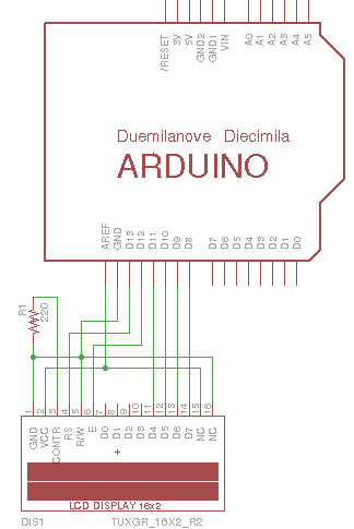
Montaje del programa para Manejo de LCD
Circuito de Conexión -LCD-

Materiales
- Pantalla LCD
- Arduino
- Resistencia 220 ohm
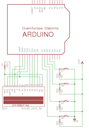
Montaje del programa para Manejo de LCD y 4 Pulsadores
Circuito de Conexión -LCD+4pulsar-

Materiales
- Pantalla LCD
- Arduino
- Resistencia 220 ohm
- 4 Pulsadores
- Resistencia 1100 ohm
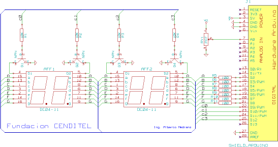
Montaje del programa para Manejo de arreglo de siete segmentos
Circuito de Conexión -Arreglo siete segmentos-

Materiales
- 4 siete segmentos
- Arduino
- Resistencia 220 ohm
